

Networking Concepts
This room is the first room in a series of four rooms dedicated to introducing the user to vital networking concepts and the most common networking protocols:
Networking Concepts (this room)
Room Prerequisites
This room expects that you know terms such as IP address and TCP port number; however, we don’t expect that the reader is able to explain such terms in proper technical depth. If you are unfamiliar with these terms, please consider joining the Pre-Security path.
Learning Objectives
By the time you finish this room, you will have learned about the following:
ISO OSI network model
IP addresses, subnets, and routing
TCP, UDP, and port numbers
How to connect to an open TCP port from the command line
OSI
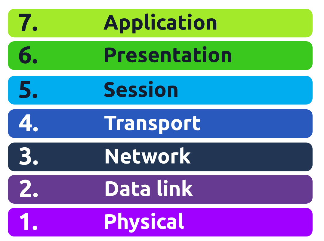
The OSI (Open Systems Interconnection) model is a conceptual model developed by the International Organization for Standardization (ISO) that describes how communications should occur in a computer network. In other words, the OSI model defines a framework for computer network communications. Although this model is theoretical, it is vital to learn and understand as it helps grasp networking concepts on a deeper level. The OSI model is composed of seven layers:
Physical Layer
Data Link Layer
Network Layer
Transport Layer
Session Layer
Presentation Layer
Application Layer
Summary
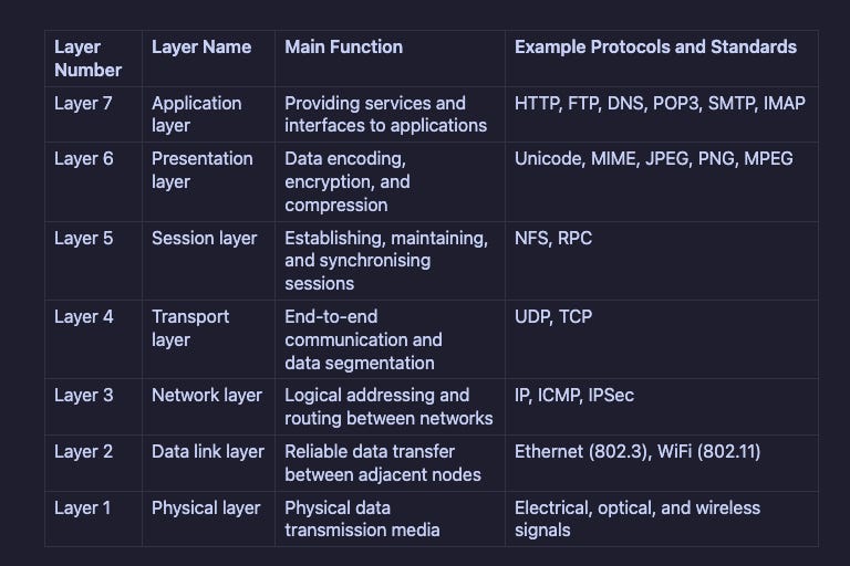
Reading about the ISO OSI model for the first time can be intimidating; however, it becomes easier as you progress in your study of networking protocols. To help with your studies, we have summarised the ISO OSI layers in the table below.
TCP/IP (Transmission Control Protocol/Internet Protocol)
The table below shows how the TCP/IP model layers map to the ISO/OSI model layers.
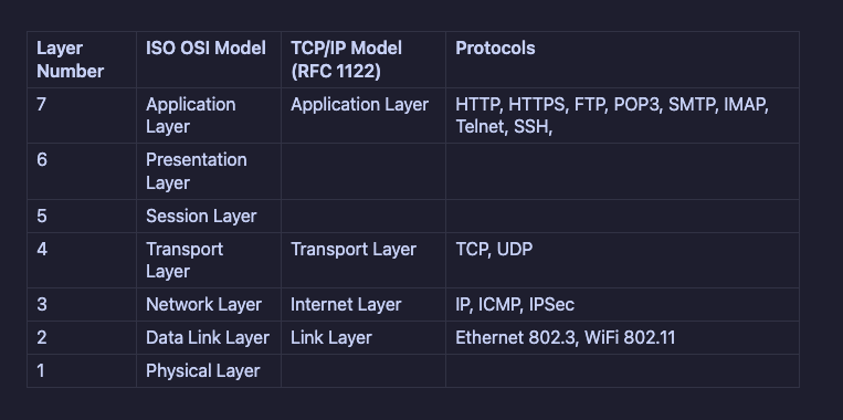
Many modern networking textbooks show the TCP/IP model as five layers instead of four. For example, in Computer Networking: A Top-Down Approach 8th Edition, Kurose and Ross(opens in new tab) describe the following five-layer Internet protocol stack by including the physical layer:
Application
Transport
Network
Link
Physical
When you hear the word IP address, you might think of an address like 192.168.0.1 or something less common, such as 172.16.159.243. In both cases, you are right. Both of these are IP addresses; IPv4 (IP version 4) addresses to be specific.
Every host on the network needs a unique identifier for other hosts to communicate with it. Without a unique identifier, the host cannot be found without ambiguity. When using the TCP/IP protocol suite, we need to assign an IP address for each device connected to the network.
One analogy of an IP address is your home postal address. Your postal address allows you to receive letters and parcels from all over the world. Furthermore, it can identify your home without ambiguity; otherwise, you cannot shop online!
As you might already know, we have IPv4 and IPv6 (IP version 6). IPv4 is still the most common, and whenever you come across a text mentioning IP without the version, we expect it to mean IPv4.
So, what makes an IP address? An IP address comprises four octets, i.e., 32 bits. Being 8 bits, an octet allows us to represent a decimal number between 0 and 255. An IP address is shown in the image below.
Looking Up Network Configuration
ifconfig
The command above should provide us with the network configuration info needed
In my instance, i have 2 active interfaces on the same subnet:
en0:192.168.0.51. Screenshot ->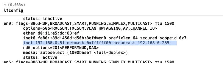
en1:192.168.0.109. Screenshot ->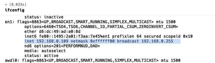
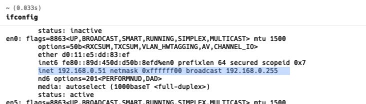
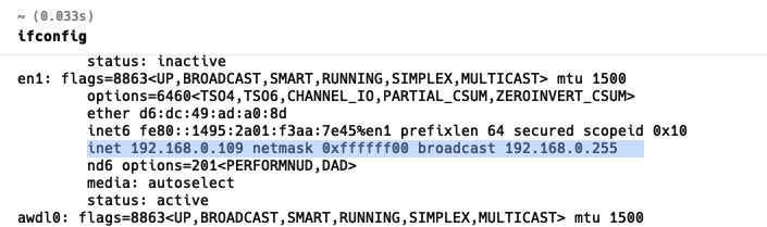
Both show broadcast 192.168.0.255 and the same netmask, so they’re both on the 192.168.0.0/24 network
Private Addresses
As we are explaining IP addresses, it is useful to mention that for most practical purposes, there are two types of IP addresses:
Public IP addresses
Private IP addresses
RFC 1918 defines the following three ranges of private IP addresses:
10.0.0.0-10.255.255.255(10/8)172.16.0.0-172.31.255.255(172.16/12)192.168.0.0-192.168.255.255(192.168/16)
We presented earlier an analogy stating that a public IP address is like your home postal address. A private IP address is different; the original idea is that it cannot reach or be reached from the outside world. It is like an isolated city or a compound, where all houses and apartments are numbered systematically and can easily exchange mail with each other, but not with the outside world. For a private IP address to access the Internet, the router must have a public IP address and must support Network Address Translation (NAT). At this stage, let’s not worry about understanding how NAT works, as we will revisit it later in this module.
Before moving on, I recommend memorising the private IP address ranges. Otherwise, you might see an IP address such as 10.1.33.7 or 172.31.33.7 and try to access it from a public IP address.
Routing
A router is like your local post office; you hand them the mail parcel, and they would know how to deliver it. If we dig deeper, you might mail something to an address in another city or country. The post office will check the address and decide where to send it next. For example, if it is to leave the country, we expect one central office to handle all shipments abroad.
In technical terms, a router forwards data packets to the proper network. Usually, a data packet passes through multiple routers before it reaches its final destination. The router functions at layer 3, inspecting the IP address and forwarding the packet to the best network (router) so the packet gets closer to its destination.
UDP
UDP (User Datagram Protocol) allows us to reach a specific process on this target host. UDP is a simple connectionless protocol that operates at the transport layer, i.e., layer 4. Being connectionless means that it does not need to establish a connection. UDP does not even provide a mechanism to know that the packet has been delivered.
An IP address identifies the host; we need a mechanism to determine the sending and receiving processes. This can be achieved by using port numbers. A port number uses two octets; consequently, it ranges between 1 and 65535; port 0 is reserved. (The number 65535 is calculated by the expression 216 − 1.)
A real-life example similar to UDP is the standard mail service, with no delivery confirmation. In other words, there is no guarantee that the UDP packet has been received successfully, similar to the case of sending a parcel using standard mail with no confirmation of delivery. In the case of standard mail, it means a cheaper cost than the mail delivery options with confirmation. In the case of UDP, it means better speed than a transport protocol that provides “confirmation.”
But what if we want a transport protocol that acknowledges received packets? The answer lies in using TCP instead of UDP.
TCP
TCP (Transmission Control Protocol) is a connection-oriented transport protocol. It uses various mechanisms to ensure reliable data delivery sent by the different processes on the networked hosts. Like UDP, it is a layer 4 protocol. Being connection-oriented, it requires the establishment of a TCP connection before any data can be sent.
In TCP, each data octet has a sequence number; this makes it easy for the receiver to identify lost or duplicated packets. The receiver, on the other hand, acknowledges the reception of data with an acknowledgement number specifying the last received octet.
A TCP connection is established using what’s called a three-way handshake. Two flags are used: SYN (Synchronize) and ACK (Acknowledgment). The packets are sent as follows:
SYN Packet: The client initiates the connection by sending a SYN packet to the server. This packet contains the client’s randomly chosen initial sequence number.
SYN-ACK Packet: The server responds to the SYN packet with a SYN-ACK packet, which adds the initial sequence number randomly chosen by the server.
ACK Packet: The three-way handshake is completed as the client sends an ACK packet to acknowledge the reception of the SYN-ACK packet.
Encapsulation
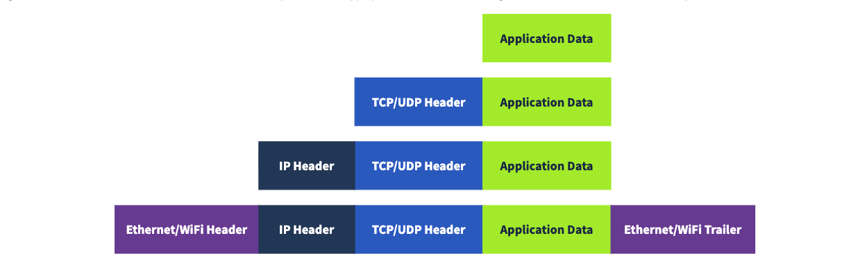
Encapsulation is an essential concept as it allows each layer to focus on its intended function. In the image below, we have the following four steps:
Application data: It all starts when the user inputs the data they want to send into the application. For example, you write an email or an instant message and hit the send button. The application formats this data and starts sending it according to the application protocol used, using the layer below it, the transport layer.
Transport protocol segment or datagram: The transport layer, such as TCP or UDP, adds the proper header information and creates the TCP segment (or UDP datagram). This segment is sent to the layer below it, the network layer.
Network packet: The network layer, i.e. the Internet layer, adds an IP header to the received TCP segment or UDP datagram. Then, this IP packet is sent to the layer below it, the data link layer.
Data link frame: The Ethernet or WiFi receives the IP packet and adds the proper header and trailer, creating a frame.
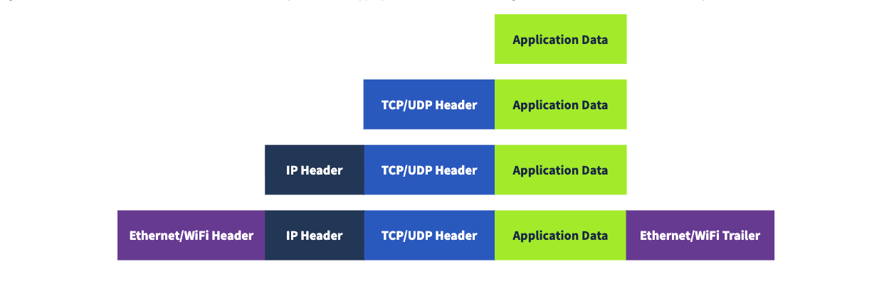
The Life of a Packet
Based on what we have studied so far, we can explain a simplified version of the packet’s life. Let’s consider the scenario where you search for a room on TryHackMe.
On the TryHackMe search page, you enter your search query and hit enter.
Your web browser, using HTTPS, prepares an HTTP request and pushes it to the layer below it, the transport layer.
The TCP layer needs to establish a connection via a three-way handshake between your browser and the TryHackMe web server. After establishing the TCP connection, it can send the HTTP request containing the search query. Each TCP segment created is sent to the layer below it, the Internet layer.
The IP layer adds the source IP address, i.e., your computer, and the destination IP address, i.e., the IP address of the TryHackMe web server. For this packet to reach the router, your laptop delivers it to the layer below it, the link layer.
Depending on the protocol, the link layer adds the proper link layer header and trailer, and the packet is sent to the router.
The router removes the link layer header and trailer, inspects the IP destination, among other fields, and routes the packet to the proper link. Each router repeats this process until it reaches the router of the target server.
TELNET
The TELNET (Teletype Network) protocol is a network protocol for remote terminal connection. In simpler words, telnet, a TELNET client allows you to connect to and communicate with a remote system and issue text commands. Although initially it was used for remote administration, we can use telnet it to connect to any server listening on a TCP port number.
Now, in order to run this on your Mac, you will need to install it. I found the easiest way is through Homebrew CLI. In your terminal, run:
brew install telnet
Echo server: This server echoes everything you send it. By default, it listens on port 7.
Daytime server: This server listens on port 13 by default and replies with the current day and time.
Web (HTTP) server: This server listens on TCP port 80 by default and serves web pages.
We will skip past this though, since we don't have a target machine for my Mac set up at the moment, but you can get that situated with a VM if you’d like.
Conclusion
Well, that pretty much wraps upps up this portion. Tune in next time for a deeper dive into Networking Essentials.


